If you do not know how to open your shutter and get to the circuits please see this page.
If you do not know how to modify your camera for AAA batteries please see this page.
Before modifying the 3xAAA holder that is included in the kit, remove about 1″ from each wire and save for later.
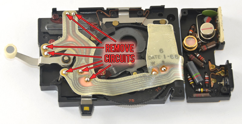
You will need to desolder the 2 power wire connections before you can remove the shutter circuit.
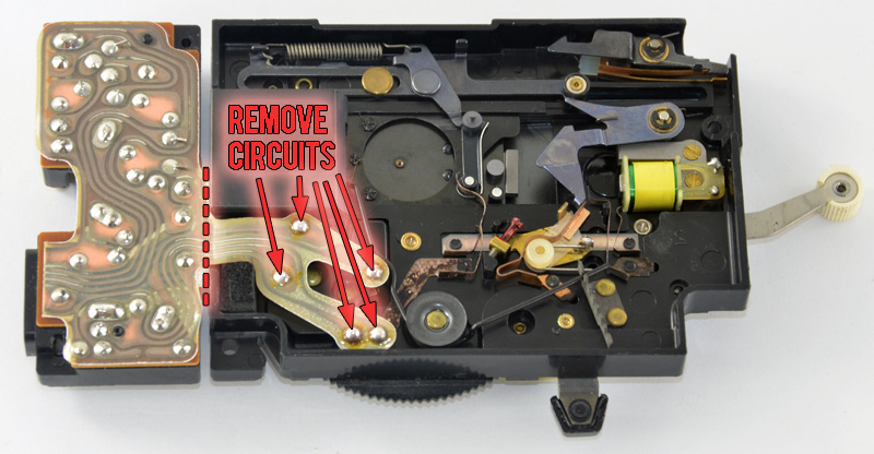
All we need is the mechanics of the shutter, so remove the flexible circuit board.
 Cut off the main circuit board which has the PC port connector for the flash.
Save this part for later.
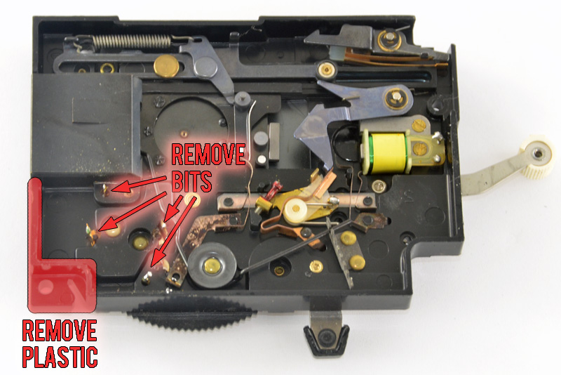 After removing the flexible circuit board, trim the little bits left over.
Also remove the plastic pieces as shown to make room for later.
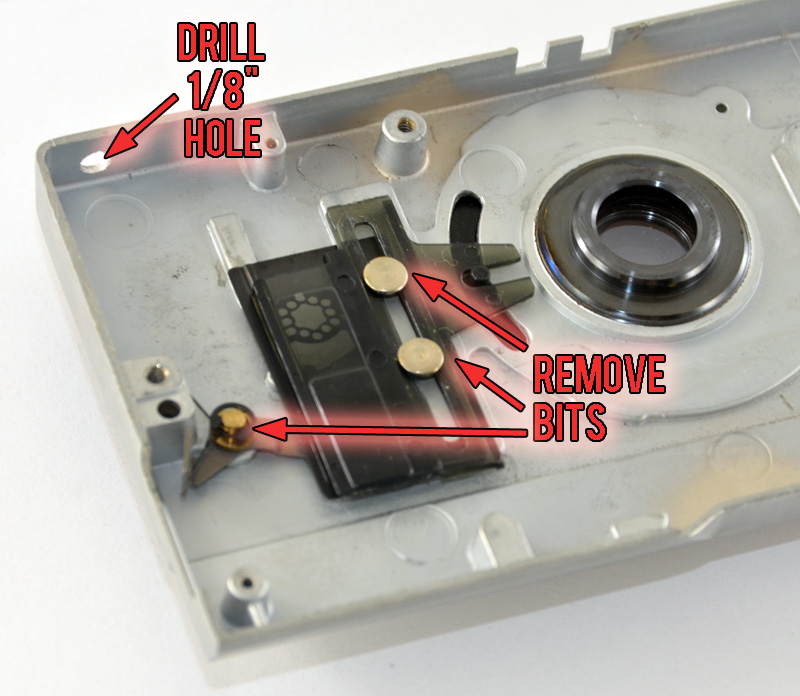 The front half of the shutter housing has some leftover electric eye pieces.
Remove them to allow the switch through. This includes removing the plastic pieces from the front of the housing such as the electric eye lens.
Drill a 1/8″ hole in the upper corner for the LED.
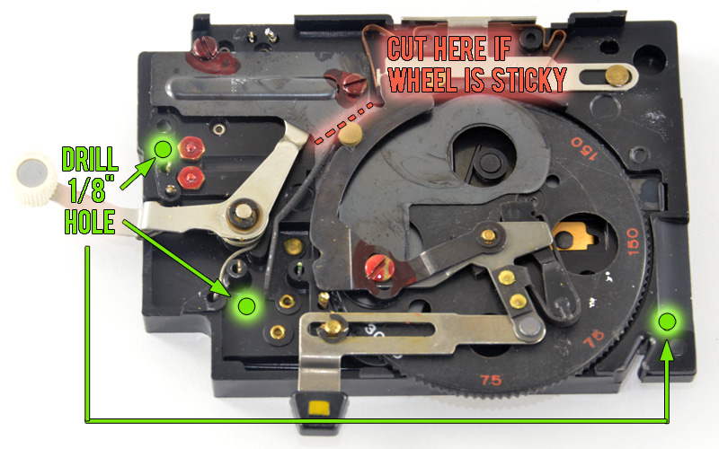 To allow the wires access from one side of the shutter mechanics to the other you need to drill 3 holes.
The aperture wheel mask, when we add the sticker later, may stick when attempting to change your aperture. If this happens you can cut it along the line outside the wheel to reduce the friction.
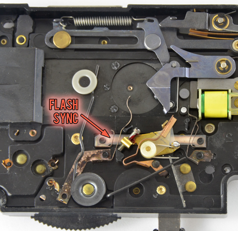 For electronic flash sync, and not flashbulb sync, you need to adjust the 2 copper contacts that control the PC port.
The two contacts need to touch when the shutter is at its maximum opening.
Have the aperture wheel set for its largest opening and use your finger to move the darkslide away from the opening.
You should now be able to see through the shutter. When the mask touches the furthest edge of the opening, thats max.
Bend the contacts so they touch at this point. (should be a tiny bit to the left)
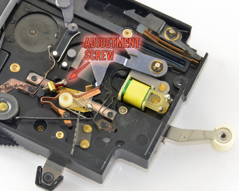 When you set the shutter notice how the hammer moves up, then down, then up again.
The hammer allows 2 copper contact together when setting the lever. And they are apart when not set.
As you set the shutter the hammer moves the 2 contacts together and apart.
Turn the adjustment screw, clockwise, so that when you set the shutter the hammer never separates the 2 contacts again until fired.
The contacts should remain apart when not set and remain together during the entire setting of the arm until it locks.