The Steps
parts & labor
what's needed to get the job done
basics of function
how does the camera usually operate; what parts do what and go where
the lensboard
removal, gutting & measuring
fitting the lens
cutting, sizing; infinity focus
final touches
painting and assembly
does it focus?
test focusing
completed
in all its glory
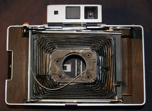
The Lensboard
This entire project is pretty much just adapting this lensboard to fit the new lens and shutter. Which requires a little cutting and some grinding.
Many Polaroids of this type have plastic rivets instead of actual screws holding the bellows to the lensboard.
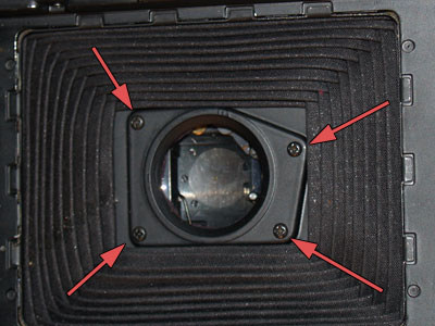
The 250 luckily uses 4 screws easily removed.
The bellows are an important part of this camera, keeping it safe is a priority.
You'll notice the cable release and battery wire still keep the bellows attached.
Since this camera will no longer need electrical power, remove the battery and its clip by taking out the single screw.
Cut the two battery terminal tips off. Pulling the wire a bit reveals a brass fitting which keeps the wire from being pulled out the front of the camera. Snip here.
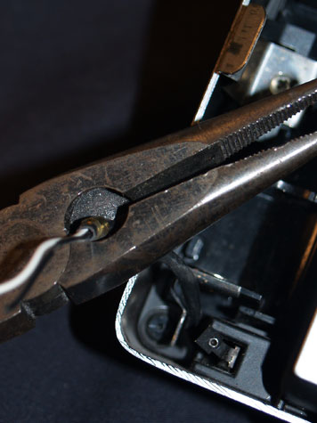
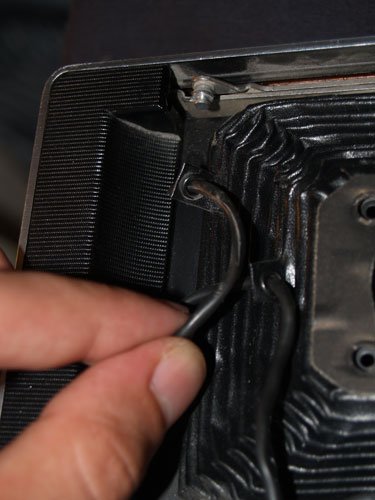
With the fitting removed, you can now pull the wire through the front, and the 2 loops on the bellows.
Just the cable release and metal arms are left before freedom!
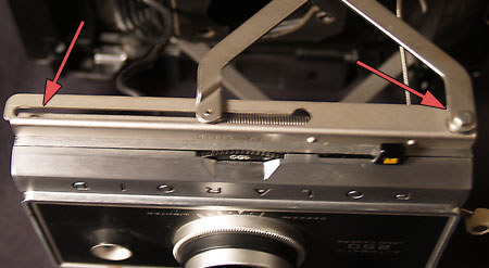
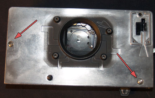
The last attachments are the 3 points held by the metal arms. The top and the bottom are connected by a single metal rod going through the lensboard. The last connection is to a spring within a slide slot.
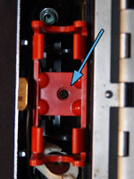
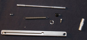
The spring arm sits within a slide held to the lensboard with a screw and by a small bolt.
Removing the bolt will cause a metal rod and washer to fall out.
The top and bottom are connected by this metal rod, unscrewing one or the other will cause both to fall out. Save these parts and remember the order in where they go.
Now slack, you can unhook the spring too.
Only the cable release holds the lensboard prisoner. Remove the screws and it can be removed. The larger top screw is one of the 3 that hold the 2 halves of the lensboard together.
Now free of the camera body, the lensboard can be worked on exclusively.
Three screws and the stuck label on the top, hold the lensboard together. First was the shutter release, the last two are on the back.
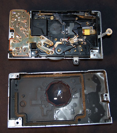
Once apart you will have two halves. One has nothing but some foam and a single lens.
The other contains everything that IS this camera. The electric eye, the chips and resistors, all that junk, its in here.
But who cares, lets rip it out of there.
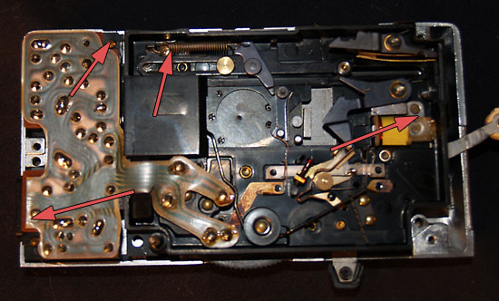
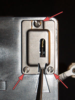
The circuitry is held by 4 screws.

Once removed you can see all the fancy doo-dads that made this baby tick.
On the lensboard you can see the mechanism behind "lighten/darken".
Toss the circuits and set the front piece aside.
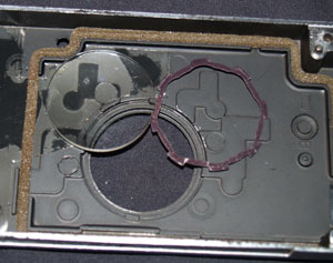
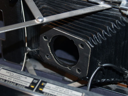
The back lens element is held in with a small retaining ring. Use a flat screwdriver to pop it out.
Use the screwdriver to also scrape that foam as best you can.
The following photos are from the last project, the 127mm lens opening is larger than what is pictured here.
Time to measure the rear lens diameter.
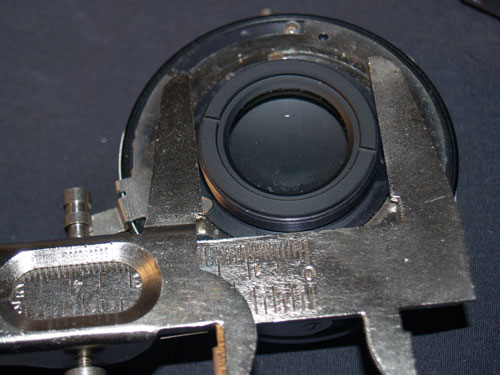
Using calipers, or a good ruler, measure your diameter.
Lock it in, or write it down.
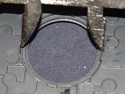
Measure the diameter of the lens against the front opening.
I will need to grind that out.