The best part about using a 160 body is that there is no need to enlarge the mirror post hole. However, you still need to drill a couple of holes and grind to get the finder assembly to fit.
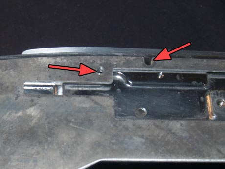
drill screw hole; drill access hole for plastic housing
First, take the finder plate and line it up.
You’ll quickly notice that only the screw hole on the left lines up.
Drill a new hole for some extra holding power, and then drill a larger hole in that notch of the plate.
access hole for housing
The larger hole will hold the plastic housing.
Without this hole, the housing will be kind of flimsy.
Make sure the hole is large enough to fit the screw through.
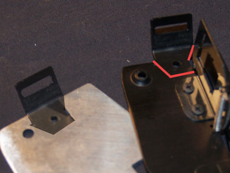
cut piece from 110A plate
If you haven’t noticed already, the 900 finder plate does not have a place for the leather strap.
You need to remove a small part from the 110A’s plate and add it to the 900 plate.
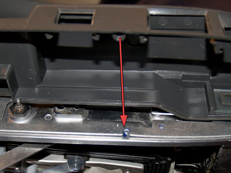
grind flat
Put the finder assembly onto the camera body.
Notice that the moving parallax frame gets stuck here.
Grind this down flat.
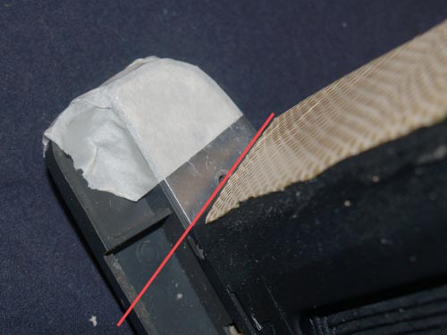
cut finder housing and plate
Before you can assemble the finder completely, the plastic housing and plate need to be trimmed for the newly mitered edge.
Tape the plate to the plastic and correctly line it up with the edge. Mark this. Cut along the mark through both metal and plastic.
But now, you have this nasty ugly edge.
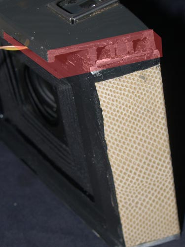
fill the red area and sand smooth
There are many ways to smooth this edge. I found Bondo to be a good solution. It lets you fill small areas and then sand smooth and rounded.
Its up to you if you want a sharp angled edge or a rounded one.
There is also the small notch in the back of the housing where the cutter bar fit, fill this too.
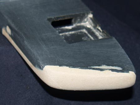
Bondo-ed and smoothed
When you are happy with how your edge looks, you should trim back the bottom rangefinder plate a bit to make sure it will fit flush with the plastic housing.
With everything ready for assembly, attach the bottom plate to the camera.
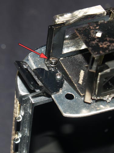
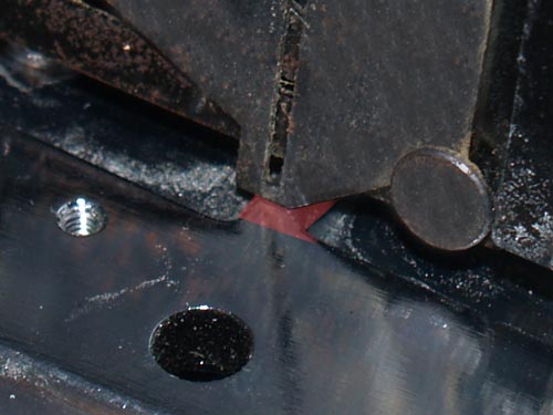
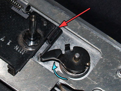
fit strap piece; align and drill finder assembly
Notice the plate has a small triangular notch, line up the finder assembly with this.
Drill a hole for a long screw, red arrow, when aligned to hold it in place.
It will take some work but grind/file the strap loop so that it will fit along the edge of the assembly.
Use a longer screw than original to hold it to the camera.
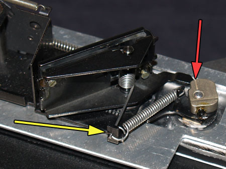
yellow:replace springs;red: align at mark
red: marked infinity; blue: place arm and press down
Replace the mirror post. Now the assembly is held fast and should not move at all. Try to move the spring arm that controls the parallax frame, if it doesn’t move freely, place a washer between the camera body and the assembly to gain some height.
Apply some pressure with pliers and the cam and arm should come off easily. Do not bend the arm!
Replace the cam arm, rotate (blue arrow) it until the mark you made for infinity is set, press it onto the post to stick.
If it seems to move a bit, use some Super Glue to hold it.
Replace the cam and mirror along with both springs, yellow. Set the cam where the line on it aligns with the similar one on the arm below it, screw it tight.
Align the mirror’s arm with the line on the cam.
Tighten the cam screw, if it still moves at all, some Super Glue again will hold it tight.
Even though its really just moving the finder from one camera to another, the double-image focusing mechanism needs adjustment..